UM on two GU29
V.Milchenko RZ3ZA
The amplifier is assembled on two parallel-connected lamps GU-29. The amplitude of the input signal is 1 ... 1.5 volts. Anode current-400...450 mA. Output power at a load of 75 ohms-150 watts.
In the transmission mode, the KT920B transistor is supplied with a voltage of -15 volts, a quiescent current, and a quiescent current of the transistor (without signal) -120 mA. Within a small range, it can be adjusted by selecting the resistor R3. Transformer T1 is shunted with a 2k resistor. The quiescent current of the lamps is set automatically by two D815D zener diodes connected in series and for two lamps is 70-80 mA. The lamps are located in a housing 300x300x80 mm horizontally. The T1 transformer is wound on a cylindrical frame with a 600НН ferrite core.
Literature: magazine "Radioamateur" No. 8 1997
UM on two lamps 6P45S


Hybrid PA with transformerless power supply
E. Golubev, RV3UB


PA with transformerless PSU and protection
For example, a PA circuit with a power supply protected from phase reversal with zero is shown. The entire article can be read: Radio magazine 1969 No. 3 p. 19
CATEGORY 1 RADIO POWER CONTROL


Literature: "Radio" 1979 No. 11 G. Ivanov (U0AFX)
Transformerless power supply in the UM


PA for MW radio
This power amplifier is designed to operate a portable radio station in stationary mode. In this case, the signal from its output is fed to the input of the amplifier through a coaxial cable. The power of a portable radio station with an input impedance of 50 ohms of a power amplifier is 1-2W. This power amplifier develops power up to 30-40W. The output is designed for a 75-ohm antenna.
The amplifier circuit is shown in the figure.
The signal from the output of the transmitter goes to the input X2 to the input of the double lamp VL1 GU-29, the signal goes to the control grids of this lamp. R7 brings the input impedance of the amplifier to 50 ohms. The anode load of the lamp is the choke L2, from which the signal enters the U-shaped filter L1 C3 C4 and then goes to the antenna. The output stage of the transmitter is equipped with an SWR meter that allows you to measure both direct and reflected SWR. This makes it possible to adjust the output circuit using capacitors C3 C4.
The power source is transformer, it contains 2 rectifiers and three parametric stabilizers.
L1 is wound with copper wire (bare) with a diameter of 2 mm, without a frame, winding diameter 25 mm, winding length 22 mm, number of turns 8. L2 is wound on a frame with a diameter of 20 mm and contains 150 turns of PELSHO 0.25, winding length 80 mm. L3 L4 are wound on resistors R2 R4, they contain 5 turns of PEV 1.0 each. L5 L6 - throttles DM-0.5. T1 - 6 turns of PEV 0.31 with a tap from the middle of a coaxial cable wound on the inner core, which goes from L1 to the output connector (the shielding braid is removed at the winding point).
T2 is wound on a magnetic circuit Ш25 * 32, winding 1 -1030 turns of PEV 0.25, 2-1300 PEV 0.25, 3-60 turns of PEV 1.0 with a tap from the middle, winding 4 contains 175 turns of PEV 0.2.
The amplifier is mounted in a metal case by volumetric mounting. If necessary, it is necessary to carry out heat dissipation using a fan to blow the lamp.
R8 sets the lamp quiescent current within 15-17mA. the alternating control voltage supplied to the grids of the lamp (U on R7) should be about 10V and not exceed 15V.
Amplifier on lamps 6P42S
The difficulty of obtaining average power levels (about 100 W) in transistorized silos forces us to look for other solutions. It can also be the same as suggested by Muscovite V. Krylov (RV3AW). He created a push-pull amplifier with two 6P42S lamps operating at a supply voltage of only 300 V. The output power of the amplifier is 130 W with an input power of about 5 W.
The push-pull switching on of the lamps makes it possible to significantly (up to 20 dB) reduce the radiation at the second harmonic compared to a conventional amplifier. A broadband transformer T1 with a transformation ratio of 4 is installed in the anode circuit of the lamps. As a result, the amplitude of the RF voltage at the output P-circuit is halved and it becomes possible to use a standard KPI from a broadcasting receiver. The simplicity of the device and the availability of the element base allow us to recommend this power amplifier for repetition. The scheme is shown in fig.

Coil L2 is made on a plastic ring (size K64x60x30) with MGTF wire with a core cross section of 0.5 mm. The taps are made from 2, 4, 8, 12 and 20 turns. Transformer T1 is made on a magnetic circuit of two rings with a size of K40x25x25 from ferrite 2000NN. The windings contain 12 turns of MGTF wire with a core cross section of 0.5 mm. The T2 transformer is made on two ferrite (2000НН) rings folded together with a size of K16x8x6. Each winding consists of 8 turns of MGTF wire with a core cross section of 0.15 mm2. Winding T1 and T2 was carried out simultaneously with three wires.
Transformerless RA on GU-29
I.Avgustovsky (RV3LE)
The idea of building a push-pull amplifier using vacuum tubes is not new, and the circuitry of this amplifier, in principle, is no different from the circuitry of building push-pull transistor amplifiers. It should be noted that current lamps work best in this circuit, i.e. lamps with low internal resistance, which are capable of providing a significant anode current pulse at low supply voltage. These are lamps of type 6P42S, 6P44S and 6P45S. However, I managed to build an amplifier with good characteristics even on a GU-29 lamp.
The range of amplified frequencies is 3.5 ... 29.7 MHz.
The power supplied to the anode circuit is 150 watts.
Efficiency - 65%.
Output power at the antenna equivalent 75 Ohm in the ranges:
o 3.5 ... 21 MHz - 100 W;
o 24 MHz - 90 W;
o 28 MHz - 75 W.
The power consumed from the network at the rated voltage in the network and the maximum output power is 200 W.
Dimensions:
o width - 160 mm;
o height - 150 mm;
o depth - 215 mm.
Weight - no more than 2 kg.
A distinctive feature of this amplifier is its transformerless power supply circuit. The advantages of such a power supply scheme are obvious - with an input power of 150 W, taking into account the efficiency of the power supply, a power transformer with an overall power of at least 200 W is required. In this case, the dimensions and weight of the power supply itself are comparable to the parameters of the power amplifier itself and far exceed the dimensions and weight of an amplifier with an input power of 500 W on 6P45S lamps.
I made this amplifier as an experimental one back in 1994, but from the very first day of operation it proved to be so good that it still works without any alterations. During this time, more than 10,000 QSOs have been made on it. All correspondents invariably note the excellent signal quality. Despite the fact that my antennas are only 2-3 meters away from the collective television antennas, TVI is completely absent.
I also want to note that the GU-29 lamp in this design is operated in a very hard mode (power input - 150 W), but despite this, for two and a half years of operation, I did not find any deterioration in power characteristics. Consider the circuit diagram (Fig. 1).

The input signal is applied to the primary winding broadband transformer based on the T1 line. The non-inductive resistor R1 is the active load of the power amplifier of the transceiver itself and allows you to get a linear frequency response of the latter.
The amplified anti-phase signal from the anodes of the lamp is fed to the transformer T2, to the midpoint of the primary winding of which the anode voltage is applied. The amplifier load is switched on through a conventional P-circuit, the signal to which is taken from the secondary winding of the T2 transformer.
The amplifier is powered through a rectifier assembled according to the voltage doubling circuit on diodes VD1, VD2 and capacitors C10, C11 (Fig. 2).

Screen grid voltage (+225 V) is stabilized. The bias voltage is obtained from a separate rectifier VD5, C9 from the secondary winding of the incandescent transformer T3.
Pay special attention to the fact that none of the sources feeding the amplifier (~6.3V, 0, -Ucm, +225V, +600V) is connected to the chassis! The amplifier chassis is used as a common wire only at high frequency.
Parts and designs of the amplifier
Since the galvanic isolation of the power supply circuits from the chassis is carried out through transformers T1 and T2, special attention should be paid to the thoroughness of their manufacture. The T1 transformer is wound on a M30VCh brand ferrite ring with an outer diameter of 16 mm (20 mm is possible). First, sharp edges are removed from the ring with fine sandpaper. Then the ring is wrapped with at least three layers of PTFE tape. The winding of the transformer is carried out simultaneously with three wires in fluoroplastic insulation MGTF-0.12 without twisting. The number of turns is 12.
The T2 transformer is similar in design to the T1, but is made on two M30VCh rings folded together with an outer diameter of 32 mm (36 mm is possible). The windings of the T2 transformer also contain 3x12 turns of MGTF-0.14 wire without twisting. The ends of the windings are fixed with threads. Polyethylene film should not be used as insulation due to its non-heat resistance.
I do not give the parameters of the P-circuit, they are easy to calculate using the available methods. In the author's version, the L3 coil is wound on a fluoroplastic ring with an outer diameter of 70 mm and a cross section of 15x15 mm2 with a silver-plated wire with a diameter of 1.5 mm and with its taps rests on a ceramic biscuit of the SA1.2 range switch. Capacitor C5 is a tuning capacitor with an air dielectric of the KPV-150 type. C8 - standard two-section PBC 2x12 ... 495 pF from broadcast receivers.
All blocking capacitors C1 ... C4, C12 ... C14 are of the KSO type for a voltage of at least 500 V or similar with a rating of 0.01 ... 0.1 μF.
In the power supply (Fig. 2), the diodes VD1 and VD2 are KD226G or KD203A, which allow a large current pulse, which is inevitable at the moment the power is turned on, since this design does not have a large inductance in the form of a power transformer. The charge current of capacitors C10 and C11 reaches tens of amperes within a few milliseconds, therefore, a resistor R6 is installed to protect the diodes VD1 and VD2 from breakdown. Its value is not critical and can range from 330 ohms to 1 kOhm. A few seconds after the amplifier is turned on, it is short-circuited by the SA3 "Anode" toggle switch. Resistors R7 and R8 serve to equalize the voltage across capacitors C10 and C11.
Transistor VT1 and zener diodes VD3 and VD4 are mounted on small heatsinks isolated from the chassis. Trimmer resistor R9 - any type, but with good insulation. Incandescent transformer - with an overall power of at least 20 W and with well-insulated windings.
Anticipating the question of readers about possible replacements for ferrite rings for transformers T1 and T2, I want to say the following: rings with a permeability of 30 VCh can be replaced without damage by any of the indicated sizes with a permeability of 20 VCh ... 50 VCh. I have not experimented with rings with a permeability of 100 NM...600 NM, and rings with a permeability of 1000 NM...3000 NM will obviously not work here.
The power supply and the amplifier lamp have galvanic contact with the network, so care should be taken during the setup process. Once again, I draw your attention: the "0V" circuit should not have contact with the chassis! The input (before T1) and output (after T2) amplifier circuits are absolutely safe and must be connected to the chassis according to the diagram.
Linear Power Amplifier for SSB/CW/AM
With an input power of 200 W, the output power is 120 ... 130 W. The amplifier operates on two GU-50 pentodes according to the scheme with three grounded gridsThe input impedance of the amplifier is 50 ... 70 Ohm, which allows you to connect it to the exciter with a piece of coaxial cable with the same impedance.
To achieve a current of 200 mA at an anode voltage of 1200 V, an excitation power of 7...10 W is required. The quiescent current is a few milliamps. Peak power (input) can be increased by amplifying single-sideband signals up to 400 watts without endangering the lamps, since the average input power will be about 200 watts. Inductor Dr1 with an inductance of about 300 ... 500 μH must be designed for a current of 200 ... 250 mA
Transistor - 600 W - PA on HF
Introduction.
The article was written during the day, I must honestly admit, as opposed to the article by Sergei - EX8A. Which directly calls everyone to return back (“backward” is the direction of movement, and “backward” is the place of arrival).
However, in addition to my own desire, there were also calls from the reading public: it’s weak to lay out something specific myself ... I answer - not weakly. Read. But I warn you that I’m not going to spread my thoughts, I won’t teach common truths - everything is in textbooks and reference books, there will be a minimum of lyrical digressions.
1. Overview of the situation.
I am sure that the idea of the impossibility of creating a PA on HF with a power of more than 1000 watts on transistors was invented by adherents of lamps. Probably because it is difficult for them to run after time and change their own stereotypes of thinking. And when they are told that there are industrial PAs for HF of 1 kW, they answer: they are industrial ones.
As for the PA on modern lamps, the fragility and fan noise are in the first place as arguments against. And instead of the modern ones, the GU-81 is offered (this is the “backward”).
2. Durability.
I do not understand why it is claimed that the durability of modern lamps is worse. In the reference books, everything is exactly the opposite. Does someone specifically put “fake” information into reference books? Or do the authors of this “idea” simply have no other way but to turn everything upside down, calling into question the data of reference books? And the answer is simple - there is no other way to justify the need for the birth of a design on OLD lamps, which, moreover, have been taken out of production for a long time due to "incompetence", but which have long since expired all conceivable shelf life.
Modern, you see, you need to train, but what about these shaggy GU-81 years? Well, of course, it cannot be said that they do not need to be trained, therefore it is so bashfully said that they say it will not be worse if they are still trained, and then they describe in detail the technology of the entire procedure.
3. Fans.
Everything is quite simple here: fans of the GU-81 are not even interested in knowing what modern fans exist there. And if you think about it, then there are 1-2 fans in the power supply of the transceiver (in my GSV-4000 there are two fans), in the transceiver itself there are 1-2 fans (in my IC-781 there are 4 of them), in the computer 1-2 fans. A total of 3-6 fans run continuously. And - nothing, they do not interfere, no one remembers them. Why? Because there are fans that have a self-noise level of 22-26 db. It's at 10!!! times quieter than a quiet conversation. Feel the difference! And they already “know how” to pump worthy volumes of air. And what cool "snails" are now! And they can also be parallelized (along the air flow) ... But if you don’t know about it, then you can, of course, scold VN-2 and the like. I've been listening to the noise of the ACOM-2000A fans, I'll tell you: nothing buzzes, nothing interferes, does not distract, and it gives 2 kW, and auto tuner available, and eight microprocessors serve the entire control and management process. And the dimensions...! And only 2 pieces of GU-74B. Will we compare further with the GU-81?
4. Power supplies.
What happens if you "short" the plus of the power source with a minus? That's right - there will be a spark. The greater the power of the power source, the greater the spark. The spark parameter is its energy (roughly, this is the instantaneous power that the power source can give). And now let's look at the power supply of the UM anodes on two GU-81. This is a voltage source of 3000 volts and a current of 1-1.5 amperes. Now look at the power supply of a 1000 watt transistor amplifier. This is a voltage source of 48 volts with a current of about 50 amperes. No matter what they say, but the energy of the spark from these sources will be approximately the same. True, there is a difference - try to touch (of course by accident) the plus of the source of the transistor PA - but nothing will happen to you, and try to also accidentally attach your finger to the anode. In the second case, have a pre-written will.
The weight of the power source for 2 GU-81s is even scary to think about, probably 30-40 kilograms. And the dimensions? It would be interesting to see a photo.
A power supply unit for a transistor amplifier has such a characteristic as a specific volume. This is 2 liters of space per 1 kW, and the weight is only 600-700 grams per 1 kW.
5. Cost.
Pertinent question. Ask on the Internet how much the amplifier for the GU-84 costs from well-known home-made "manufacturers" - the answer is simple - at least 2000 USD, and for the GU-78B it is already just 100,000 rubles. And then - not earlier than in 2-3 months you will be able to receive it. True, we must honestly say that everything was done well, soundly, for a long time. There is already experience in the long-term operation of such amplifiers - 5-7 years without breakdowns and replacement of lamps (lamps - to the displeasure of GU-81 lovers - cermet, modern lamps). Who said that an amplifier based on transistors of the same power should cost less? And with self-production, it really and really costs less. A recent example: a radio amateur from St. Petersburg bought a GU-91B with a socket and a fan for 450 USD, for an amplifier that was made in Ukraine for 2000 USD. The price for a used ACOM-2000A starts from 3500 USD. And you ask a UM lover at GU-81 how much he would sell it for? At best, he will say that he is not for sale.
The price of a selected pair of transistors for a 600 watt PA is in the range of 250-300 USD. This time. BP - impulse. I use 2 computer power supplies of 750 watts each. A pair costs 150 USD. This is two.
Of course, there are no 10 pieces of relay P1D or V1V, or even B2V. There is no range switch. There is no stupid setting of the P-loop, but this is one or two capacitors and a variometer. And so on, with all the "stops". This is three.
The rest of the cost of the entire UM is slightly growing due to the price of the housing, filter, bypass relay and other small things.
If, using an adder, we add the powers of two output stages of 600 watts each to get 1200 watts at the output, then, consequently, all costs must be almost doubled. Where can I buy UM for 1200 watts for 900-1000 USD? And with such dimensions, and with such weight? The answer is nowhere.
6. Scheme.
Yes, nothing special, no "tricks" - the most common push-pull scheme.
On one UM board.
Or like this one:

See in more detail:

on the second - bypass relay, on the third - output range filters, on the fourth bias source of the base circuits. Supply voltage - 48v. The output stage quiescent current is 150-250 mA. Transistors TH-430pp. Ferrites - TDK. The windings of the output transformer are stranded silver wire 2.5-4 mm2 (no more than 1 meter).
Adder transformers are a separate issue. Since the scheme can be found in any literature, I will not cite it. I show detailed photos - everything should be clear.
Here's everything assembled on the radiator:


7. Element base.
Again, nothing special - powerful transistors, transformers.

7. Perspectives.
Here on this ONE such "handsome" you can get 400-600 watts per HF.

A push-pull circuit will easily deliver over 1000 watts. Two modules - will give more than 2000 watts. The weight of one 600-watt module is 2 kg (with heatsink and fans). The weight of one PSU is 0.65 kg. Case - weight 1.5 kg. The surface area of the radiator is about 2000 cm2, the fins are blown from the side by two computer coolers. The whole thing weighs less than 5 kg.
And I also want to make this automatic and inexpensive 200 watt tuner work with a power of about 1000 watts, replacing the elements of the matching device with more powerful ones.

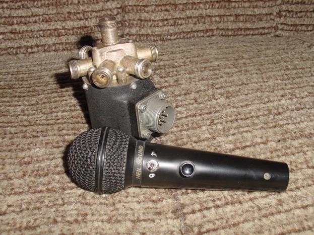
Microphone HEIL SOUND HM-10-5 with two "pills" (different frequency ranges) is here to understand the size.
This is an industrial 500 watt amplifier on two MRF-150s that I took out ;).

And this is its reverse side.

It was not possible to quickly find an industrial amplifier for 1 kW of the same plan, only it has radiator fins three times higher, and there are two parallel amplification channels on the board with an adder between them at the output.
QUESTIONS???
Part 2. Transistor - 600 W - PA on HF
Thanks to everyone who responded to the article. Even those who thought that I was a rogue, and this article is nothing more than a "divorce" and deception.
Fans. Wonderful article by N.Filenko. UA9XBI here on -, I see no point in quoting and repeating. I can only give some figures for orientation: An average hard drive emits noise (average between the standby state and the search state) at the level of 30-35 dB (decibels). For comparison: a whisper - 10-20 dB, a calm human voice - 50-60 dB, a moving train - 90 dB, an airplane taking off - 120 dB, a pain threshold - more than 130 dB. As for combat use: office noise (printers, fax machines, copiers, etc.) - 50 dB, noise in a residential area - 30-40 dB, computer fan noise- 20-34 dB. Want to buy a normal fan, please: http://www.zifrovoi.ru/catalog/coolers/all/
Photos. It seems that this is where some people try to find a catch. I ordered and bought the first board in Japan, and posted the same pictures only because they were made more beautifully on a blue background (I think so). There is no secret in this. But if it seems to someone that this is not so, please use the same board (again with my microphone).

Power. Now I will shoot everything on my sofa J). Here is another UM

On a piece of paper, which is attached to the board with a wire, the output power by ranges is written. The resolution of all photographs is sufficient so that you can see everything in great detail. What we see there: in the ranges of 7, 10, 14, 18 MHz, it gives out 500 watts. You see, it is written there - with a supply voltage of 28 V and an input power of 10 W on all ranges.
At 3.5 and 21 MHz, respectively - 320 watts and 400 watts. At 1.9 MHz - 200 watts, 24 MHz - 240 watts, and at 28 MHz 160 watts. Thus, at a level of -3 dB (which is half the power), the frequency range of the amplifier is 1.9 - 24 MHz. Doubling the power changes the S-meter signal level by only 0.5 points. At a frequency of 28 MHz, the received signal level will drop by 0.7 points. By the way, it should be noted that the opening angle of the antennas is determined in exactly the same way - by the level of half power, i.e. -3 dB level.
In order to raise the output power by 1.9, 24 and 28 MHz, you just need to increase the input power by 2-3 times (20-30W). Or make an ALC system - automatic power level control. I did not do this, because. I find it easier to turn the RFPWR knob.
This power is given by the board that you see in the photo. I have no doubts that when powered from a 48 V source, and with constructive optimization of transformers, this board can deliver “a little more” power. And if you add a couple of such modules - here you have 1000 watts. Now think, is it worth striving for 2000 watts if, as a result, you get an increase in the signal level at the receiving end of only 0.5 points? An example of my neighbor's work, I will not name his call sign. At 20-ke I receive it at 9 + 50 dB (S-meter is calibrated), and I hear the second harmonic at 28 MHz at 9 + 5 dB. In man good antenna(biggun5 el), but the amplifier ... is made impeccably, neatly, beautifully, it tells everyone that I have an honest "two hundred kilos". And there are two GMI-11 lamps in parallel and an anode voltage of 2500 volts. How is that? Fine? No amount of persuasion helps. And even though a good engineer himself understands that a decrease in the level of 0.5 points is nonsense, he does NOTHING.
I have a GU-73P amplifier, cooled with some kind of refrigerant. And the power supply to it, which I was already too lazy to photograph. I never turned it on (it gives 2500 watts), the PSU weighs about 50 kg. They wanted to somehow steal it because of the aluminum sheathing, but they couldn't raise the hi-hi.
Power supplies. First, a photo of a pulsed power supply from a well-known American company

This UPS provides 20 volts and 125 amps for a total of 2500 watts. Weight - about 12-15 kg. When examining the RZ3CC on the table, it turned out that it was absolutely not suitable for our applications. At the moments of switching of the key transistors, such pulses jump, which makes it even uninteresting to look for options for protecting the receiver from them. True, I must say that this is a development of about 15 years ago, and then, of course, they still did not know about resonant UPSs. The bottom line is that the principle of operation of the converters that are used in power supplies for modern transceivers is not suitable for high powers.
Now let's look at the UPS that I use.

This is understandable - a computer UPS. For those who said something about high currents - enlarge the picture and see the inscription 5v / 50a - no bolts and nuts. This I mean that nothing prevents you from making a connection, for example, even with a ribbon cable.

There are two UPSs here, the top 5v / 20a, the bottom 5v / 90a. The movement forward is noticeable - UPSs have become noticeably smaller and lighter. In the IC-781 500W UPS, the power supply has very small dimensions and a weight of about 1.5-2 kg, but it is already more than 15 years old. Agree that technology has come a long way.

In a 750 W UPS for a computer, there are already two windings of 12v / 22a each. Take two of these UPS and get 48v / 22a of input power. Just do not forget to decouple the sources with diodes. If you do a little magic with other voltages of these UPSs, you can get an input power of 1600W.
My output stage worked with a traditional SP - transformer, in the photo below you see a bus with which OSM -1 1.0 is wound, by the way, its price on the Internet is 2930 rubles.

Winding with such a tire does not greatly raise enthusiasm, and the weight of the transformer turns out to be quite rather big.
I have already said that I treat lamps NORMALLY, they will be out of competition in the industry for a long time. But still I want something more compact and light. It turned out - they do it, though not for a wide audience. In one research institute, I was offered a pulse power supply unit for a tube PA. They said this: 3000v, 1.5a, in a case, with protection, with reliability of the highest class, in a volume of 3 liters, weighing 2-3 kg, all elements are imported (only Epcos ferrites), for 30,000 rubles, for 1 month. I asked, can I see the diagram, the answer is 15,000 rubles, and the diagram with a detailed description is yours. I didn't buy the plan. But I realized that there are options that are very interesting for radio amateurs.


This is a kilowatt module powered by two GI-46Bs. Fans and heatsinks from the processor. The area of the radiator for each lamp is 850 cm2, which is almost twice as much as that of the "native" radiator. This idea has so far been stopped in its incarnation, due to the appearance of an alternative one - on transistors.
Scheme. I will give both schemes that I received.


As I said - nothing unusual - the most standard schemes. The quiescent current of each transistor is 150-250 mA. As for ferrites, I strongly would not advise using our ferrites at all. There is only one reason - the instability of the parameters. Red has several options for ferrites - choose any that is suitable for power and frequency. Output transformers: I have several options - blue ferrites are AmidonFT-23-43, diameter 23mm, material 43, 6 pieces in each column. 4 turns of wire with a cross section of 1.5 mm square. In the second amplifier of the ring TDKK6a.77.08, the outer diameter is 28mm, the inner diameter is 16mm, the height of the ring is 8mm. Two rings in each column. Four turns of stranded silver wire, with a cross section of 2-2.5 mm square. Input transformers - rings vn. Diam. 14-16 mm, int. - 8 mm, the length of the columns - 14-18 mm, material M600NN. Four turns of wire with a cross section of 0.35 mm square. The dimensions of the ferrite rings in transformers depend solely on the power loss. It is for this reason that with exact matching, the dimensions of the rings can be very small. As an example, in the next photo - a block of band-pass filters from 500 W, ICOM, which was presented to me by RZ3CC (G. Shulgin).

Remember to install high voltage ceramic capacitors where they are shown on the diagram.
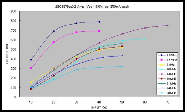

Shown here are measurements of output versus input power. Not my measurements. The first picture is American, the second is Japanese. But the order of capacities is quite obvious, I would say much better than on the GU-74B, and only two 2SC2879. Well, the last plate from the Japanese, look - very characteristic. This is a pair of MRF448pp transistors, according to the datasheet they have a power of 250 watts, and they give more than 250x2.
Pin (W) Pout (W) Vip (V) Ip (A) Pip (W) Efficiency (%)
1 82 48.3 7 338 24.3 2 177 48.3 12 580 30.5 5 380 47.8 19 908 41.8 10 530 46.5 24 1116 47.5 14 630 46.0 25 1196 52.7
Coordination. I want to pay special attention to matching with the antenna of the transistor PA. Of course, it is best to use automatic antenna tuner(By the way, someone on the forum thought I wanted to cram three times as many variable capacitances and inductances into the same volume. That's a very bold hi-hi guess), but you also need to have decent antennas, or at least , manual matching device. I don’t understand the statements that the lamp will “hold” a large SWR, unlike a transistor. And at the same time, he is not at all interested in the fact that at the same time all the TVs in the district will go out and not only phones, but also irons will start talking. But “we work” on Alpha, or on something else, no less than one kilowatt. The protection of the transistor PA is quite simple, I wrote about it in the forum in my opinion RK3AQW. I do the same, but I limit the critical SWR not to 10 but to 6. That is, the amplifier output is loaded on a non-inductive resistor with a resistance of 300 ohms. This is a price to pay for the reliability of the amplifier as a whole. This resistor consists of 2, one 270 ohm, and the second building coal 47 ohm. From the engine of this resistor, through a pair of diodes with a capacitor, the voltage is supplied to the base of the transistor switch on 2N2222, in the collector of which there is a RES-49, which removes the bias voltage from the output stage with its contacts. Since SWR = 6 transistors can “tolerate” for a long time, during this time the offset is completely calmly removed. Well, then - repair or tune the antenna.
UM in 1 kW
.
And this is the back view.

From the side of the details, it can be seen that there are two channels, two IPs are connected, there is an adder. Please note that a piece of a cut coaxial cable is visible on the right - the output. I note separately - its diameter is 2.5 mm. I think that for powers of 1000 watts or more, our people use cables with an outer diameter of 11-15 mm. Here, 2.5 mm will probably cause an uproar. But there is an RG-142 cable, the diameter of which with an outer sheath is 4.95 mm, which is capable of transmitting a power of 3.5 kW at a frequency of 50 MHz. And also pay attention to the size of the ferrites - there are no hints of gigantic sizes. Etc.

This is a rather "old" microphone processor, it has a compressor, reverb, some kind of built-in melody, a monitor from the receiver, a level indicator. The next photo is a modern device for the same purpose.


This is an inexpensive VHF 150W standard PA, which can easily fit 600W PA HF, although the heat sink is rather weak, but it can be blown with a cooler or replaced. And the amplifier that is inside can be easily converted to HF watts that way by 250.

Microphone graphic equalizer. The good thing is that in the 3 kHz band it has 5 bands of active adjustments.

This, for example, a microphone switcher, can switch two different microphones to two different transceivers in any order (HF and VHF, for example).
This is a three-kilowatt coaxial antenna switch for 6 antennas.

This is a TVI filter.

And the time for this miracle, at least for radio amateurs, should be over.
73! RU3BT. Sergey
From the practice of designing tube HF amplifiers
Probably every radio amateur, especially those working on the low bands, would like to have a compact power amplifier with good efficiency, compatible with modern HF transceivers, now, as a rule, imported, having a decent appearance that would decorate and give solidity to our radio shacks, and , most importantly, had high reliability and pleased with his work.
Well, where - where, and thank God we have such excellent and quite affordable radio tubes in Russia as GU 50, GI 7 B, GMI 11, GU 46, GU 43 B, GU 91 B, GU 78 B, etc. which are valued all over the world. After all, if you correctly prepare a radio tube for operation, even if it has lain idle for more than a dozen years, and comply with the necessary requirements and operating modes, then one such lamp will last for many years. The failure of the radio tube due to static or surges in the supply network is unlikely with a reasonable circuit design, the radio tube is not afraid of mismatch and prolonged overheating and overload.
When developing the output stage, you do not need to play it safe and use transformers in power supplies, filter capacitors and other radio elements that exceed the required values in power, capacity and size, otherwise it will look like a bicycle with truck wheels. Instead of the expected high parameters, reliability will decrease, especially at the moments when high-voltage sources are turned on and in the first seconds of warming up the glow of radio tubes. The design should be built on the basis of a reasonable compromise, taking into account all parties, only then it is possible to achieve high reliability, the required parameters, dimensions and weight.
If, for some reason, such radio elements are used, then you will have to complicate the circuit and use devices that smooth out extra currents, use a time delay relay, and protect the computer from surges in the network, if it is used. But you must always remember that every extra contact, every extra semiconductor is an element of unreliability, especially in the output stage.
I would like to dwell on the power supply circuits for the incandescence of radio tubes. It is necessary to choose the right voltage from the large tolerance indicated in the passport, which ensures the long-term operation of the radio tube, not every unified transformer is suitable for this.
Now there are many diodes with excellent parameters, and the RF elements of the output stages of military radio stations: coils; panels for lamps; KPI, including vacuum ones, with excellent overlap; switches; relay V2V, P1D, etc. This is of course the ultimate dream. If you approach this wisely and do not put a coil from a 20 x 3 bus in a cascade on the GU 82B, then you can get quite acceptable dimensions. It is convenient to use two-block designs when the power source is under the table, then the output stage itself will turn out to be more compact.
Low-current relays, including reed relays, easily provide control of the main contactors of the amplifier and interface with the transceiver, both for switching ranges and for controlling reception / transmission.
When designing a cascade, it is important to know if it will be used in contests, FM, CW, etc., or if the cascade is intended purely for everyday amateur radio communication. All this affects the weight, dimensions, blowing modes. The correct choice of the circuit for switching on a radio tube with a common cathode or a common grid can help out, this is very important !!!
Such modes are undesirable when from three GU 50 they receive 500 W in the antenna, in this case you will have to have a supply of lamps. There is no point in this, because there are more powerful lamps, and even more so, for example, if you had a power of 300 W, and you increased it to 500, then almost no one of this increase of 2 db (0.3 points) will notice.
It is not superfluous to install at least LEDs on the front panel that control the currents of the grids and indicate the operation of the cascade in the appropriate modes.
The circuit with parallel power supply of the anode circuit, which is loved by many designers, justifies itself when using lamps with a small output capacitance and the initial capacitance of the anode KPI, but it also has its own difficulties - you need to correctly perform the anode choke, it is important to know its resonant frequency, which can be determined using an RF voltmeter . The resonant frequency of the inductor should not be near the amateur radio bands. It is advisable to stipulate somewhere a ban on transmission at this frequency, otherwise, with modern transceivers with continuous overlap up to 30 MHz, turning the knobs of the encoder to the resonant frequency of the throttle can disable the power amplifier.
If a lamp with a large output capacitance of tens of pF of the GU 81 type is used in the PA and at a high anode voltage that increases Re or using a KPI with a large initial capacitance, it is advisable to use a circuit with a series supply of the anode circuit, use incomplete inclusion of the elements of the oscillatory system. High-quality high-capacity high-capacity capacitors for a voltage of at least twice the anode voltage should be placed in front of the output stage tuning elements in order to remove the constant component, and, at the same time, not to reduce the capacitance of the KPI. The range switch in such a circuit is subject to increased requirements, since it is under high voltage and must be reliably isolated from the case, and the axis of the control knob is separated by a dielectric RF insert.
Based on many years of observations, I can’t say anything negative about the use of low power in the PA - up to 1 KW of electrolytic capacitors in anode voltage sources. It is only necessary to ensure that the voltage on each capacitor is no more than 85% of the voltage indicated on the capacitor case, and try not to place electrolytic capacitors near the heating elements of the cascade. There have been cases of failure of capacitors of the K 50-17 1000uF / 400v type, etc., where the output copper terminals have aluminum rivets - over time, of course, the contact is broken. It is clear that in more powerful output stages, the use of metal-paper and combined type capacitors (K 75) is preferable.
It is clear that it is difficult to specify all the subtleties, but if at least these points are taken into account, then the cascade will work reliably, linearly, without expanding the bands, and without creating out-of-band emissions. Surely many radio amateurs have done all this. But the normal operation of even such a cascade can be easily spoiled by increasing the signal level from the transceiver beyond the norm or distorting the input signal by excessive compression and overload on the microphone input.
As in any business, one should not expect quick results and the first dozens of designs will not be entirely successful, somehow: not the optimal ratio of dimensions, weight, power output, design in general, the operation of cooling systems, the location of controls and controls, ease of use , reliability of the cascade during fluctuations in the supply network, elevated temperatures, operation for non-standard loads, etc. But with years of observation, analysis, work on the bugs and of course daily work, for sure something will start to work out.
Now a little about the psychological moments. You can hear such reasoning: “I used to have UM on GK 71, this is a thing, but now no one hears me on GK 13.” This is of course ridiculous, but such a delusion has taken root in a person, it is difficult for him to prove that these are one and the same, and that this is from the area “when the trees were large”. Do not believe these sometimes pleasant memories and impressions, but only believe the arrow of the power meter at the output of your cascade. I naturally omit all talk about antennas and transmission as a matter of course and play an important role.
I would like to make the following observations:
- if you doubled the power, for example, from 100 to 200 W, then almost no one will notice this, but they will say: “Probably QSB”;
- if you increased the power by 4 times, you got an increase of 1 point (6 db), but not everyone will pay attention to this, but only an experienced correspondent;
- an increase in power by 10 times more than 1.5 points (10 db) is noticed by almost everyone, although estimates can be from 3 to 20 db;
- 16 times - 2 points (12 db), pay tribute to the work of the output stage;
- 64 times the power increase is 3 points (18db), comments are superfluous, and estimates can be from 10 to 40 db.
Such experiments must be carried out very quickly, to minimize the influence of QSB, clearly indicate the positions and be sure to monitor the matching and real feedback to the antenna, each time you turn it on.
This must be taken into account in order not to place unreasonable hopes on one or another output stage, but to realistically assess its capabilities and imagine what effect it will have.


More details can be found: www.afaru.ru/rz3ah
A. ROGOV (
RZ3AH)
Moscow tel. 909–50–13
I present to your attention a power amplifier for a HF transceiver on field-effect transistors IRF510.
With an input power of about 1 watt, the output is easily 100-150 watts.
I apologize in advance for the quality of the diagram.
The amplifier is two-stage. Both cascades are made on popular and cheap key mosfets, which distinguishes this design from many others. The first cascade is single-cycle. Input matching with a 50 ohm signal source is not the best, but in a simple way- using a resistor R4 with a nominal value of 51 Ohm at the input. The cascade load is the primary winding of the interstage matching transformer. The cascade is covered by a negative feedback circuit to equalize the frequency response. L1, included in this circuit, reduces the feedback in the higher frequencies and thereby raises the gain. The same purpose is pursued by setting C1 in parallel with the resistor at the source of the transistor. The second stage is two-stroke. In order to minimize harmonics, a separate shift of the cascade arms is applied. Each shoulder is also covered by the OOS chain. The cascade load is transformer Tr3, and Tr2 provides coordination and transition to an unbalanced load. The offset of each stage and, accordingly, the quiescent current, are set separately using trimmers. Voltage is applied to these resistors through the PTT switch on transistor T6. Switching to TX occurs when the PTT point is shorted to ground. The bias voltage is stabilized at 5V by an integrated regulator. In general, a very simple circuit with good performance.
Now for the details. All amplifier transistors are IRF510. Others can be used, but with them one can expect an increase in the gain cutoff in the frequency range above 20 MHz, since the input and through capacitances of the IRF-510 transistors are the lowest of the entire line of key mosfets. If you can find MS-1307 transistors, then you can count on a significant improvement in the performance of the amplifier in the higher frequencies. But they are expensive ... The inductance of the Dr1 and Dr2 chokes is not critical - they are wound on 1000NN ferrite rings with 0.8 wire in one layer until filled. All capacitors are smd. Capacitors C5, C6 and especially C14, C15 must have sufficient reactive power. If necessary, you can use several capacitors connected in parallel. To ensure the high-quality operation of the amplifier, special attention must be paid to the manufacture of transformers. Tr3 is wound on a 600NN ferrite ring with an outer diameter of 22 mm and contains 2 windings of 7 turns. It is wound in two wires, which are slightly twisted. Wire - PEL-2 0.9.
Tr1 and Tr2 - are made according to the classical design of a single-turn SPT (aka "binoculars"). Tr1 is made on 10 rings (2 columns of 5) of ferrite 1000NN with a diameter of 12mm. The windings are made with thick MGTF wire. The first contains 5 turns, the second - 2 turns. Good results are obtained by making windings from several wires of smaller cross section connected in parallel. Tr2 is made using ferrite tubes taken from the signal cords of the monitors. Copper tubes are tightly inserted inside their holes, which form one turn - the primary winding. A secondary winding is wound inside, which contains 4 turns and is made with MGTF wire. (7 wires in parallel). In this circuit, there are no elements to protect the output stage from high SWR, except for built-in constructive diodes that effectively protect transistors from "instantaneous" overvoltages on the drains. SWR protection is handled by a separate node, built on the basis of an SWR meter and reducing the supply voltage when the SWR rises above a certain limit. This scheme is the topic of a separate article. Resistors R1-R4, R7-R9, R17, R10, R11 - type MLT-1.R6 - MLT-2. R13, R12 - MLT-0.5. The rest are smd 0.25 watts.
The amplifier is designed for linear amplification of single-sideband, telegraph and AM signals in the ranges of 10 ... 80 m. When amplifying telegraph and AM signals (in carrier mode), the input power is 200 W, while amplifying single-sideband signals, the average input power (when pronouncing a long “a” in front of the microphone) is also 200 W, while "the peak input power can reach 400-500 W. The efficiency of the amplifier is 65-70%, depending on the operating range. The amplifier uses four G811 lamps connected in parallel according to the OS circuit (Fig. 1).
 A. Jankowski (SP3PJ)
Despite the general trend of using semiconductor devices in all technical devices, it is still necessary to remember that tube HF power amplifiers (with an output power of more than 100 W) are much easier to manufacture and more stable in operation. Experimenting with transistor devices is an expensive pleasure, because, as someone aptly noted, no one dies as quietly, as quickly and surely as a transistor.
Who needs power amplifiers? Few of the amateurs work QRP, but most sooner or later begin to dream of increasing the power of the transmitter. However, you must be aware that in order for the correspondent to notice a change in signal strength by one point on the S scale (6 dB), the output power of the transmitter must be quadrupled, it does not matter if this is a local connection or a QSO with DX.
 Vyacheslav Fedorchenko (RZ3TI), Dzerzhinsk, Nizhny Novgorod Region Many radio amateurs design short-wave power amplifiers on direct incandescent lamps, such as GU-13, GK-71, GU-81. These lamps are not expensive, unpretentious in operation, have a high linear characteristic and do not require forced cooling. The main positive quality of these lamps is their readiness for operation in one or two seconds after power is applied. According to the proposed description, more than a dozen designs were made, which showed excellent results. specifications, good repeatability, easy to set up and operate. The design is designed for repetition by radio amateurs of average qualification.
 V. Gnidin UR8UM (ex, UR4UAS) Based on the amplifier circuit from the article by V. Drogan (UY0UY). “HF Power Amplifiers” I simplified the circuit a little, redoing it for the parts I have, so to speak, a budget option. I offer to review what happened.
 Oleg Platonov (RA9FMN), Perm
This amplifier operates on the amateur bands 3.5-28 MHz. With an input signal power of 25 ... 30 W, its output power in SSB mode on the 3.5-21 MHz bands will be at least 600 W and at least 500 W on the 24 and 28 MHz bands. The input impedance of the amplifier is 50 ohms.
It is made on two pulse generator tetrodes GMI-11, connected in parallel according to the scheme with a common cathode
With the help of a hybrid amplification scheme and impedance matching by the input P-circuit, we swing the signal to a power of 150-160W at an anode current of two GU-50s - about 300mA in the key-pressing mode. Also, it is desirable to control the current of the screen grids and not exceed its value of more than 40mA for two lamps. 250V x 0.02A = 5W - the maximum allowable level of power dissipation on the screen grid for one lamp. A protective diode will protect the stabilizer transistor in the event of a lamp shooting through the grid.
Usually, a power amplifier for a radio station or a HF transceiver is built on lamps of the “GU ...” type or on powerful high-frequency transistors. Both of these options may not always be acceptable. Lamps of the "GU" series are relatively scarce, and powerful RF transistors, although they can be purchased, are prohibitively expensive. In addition, to build an output stage with a power of more than 100 W, you will need several of these transistors, plus more labor-intensive high-frequency transformers. The power amplifier described in this article is built according to a hybrid circuit on two relatively affordable transistors (KT610A and KT922V) of medium power, and one 6P45S lamp, which was widely used in the horizontal scanning output stages of tube TVs and, in this regard, is also relatively available and cheap.
I. AVGUSTOVSKY (RV3LE), Smolensk region, Gagarin The idea of building a push-pull amplifier based on vacuum tubes is not new, and the circuitry of this amplifier, in principle, is no different from the circuitry of building push-pull amplifiers based on transistors. It should be noted that current lamps work best in this circuit, i.e. lamps with low internal resistance, which are capable of providing a significant anode current pulse at low supply voltage. These are lamps of type 6P42S, 6P44S and 6P45S. However, I managed to build an amplifier with good characteristics even on a GU-29 lamp.